Making a Mouse-less Navigator for a 3D Modelling Software
About a month ago I saw this video on YouTube by SpaceX where Elon Musk controlled the orientation of a 3D model using his bare hands. The video got me thinking, such a device would actually be useful for me and probably many others who work with 3D modelling software. The only problem is, us normal people with normal amounts of money can’t really afford such a device. So I decided to attempt to make one myself.
Admittedly, unlike in the video by SpaceX, I did decide to go with a physical device that fits on the hand. I had neither the dataset nor the computing capabilities to create something usable without attaching anything physically. I’ll be talking more about this later.
The Controls
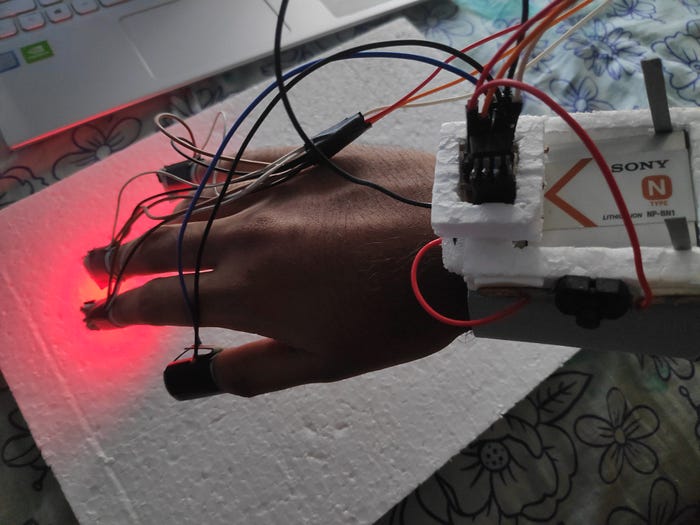
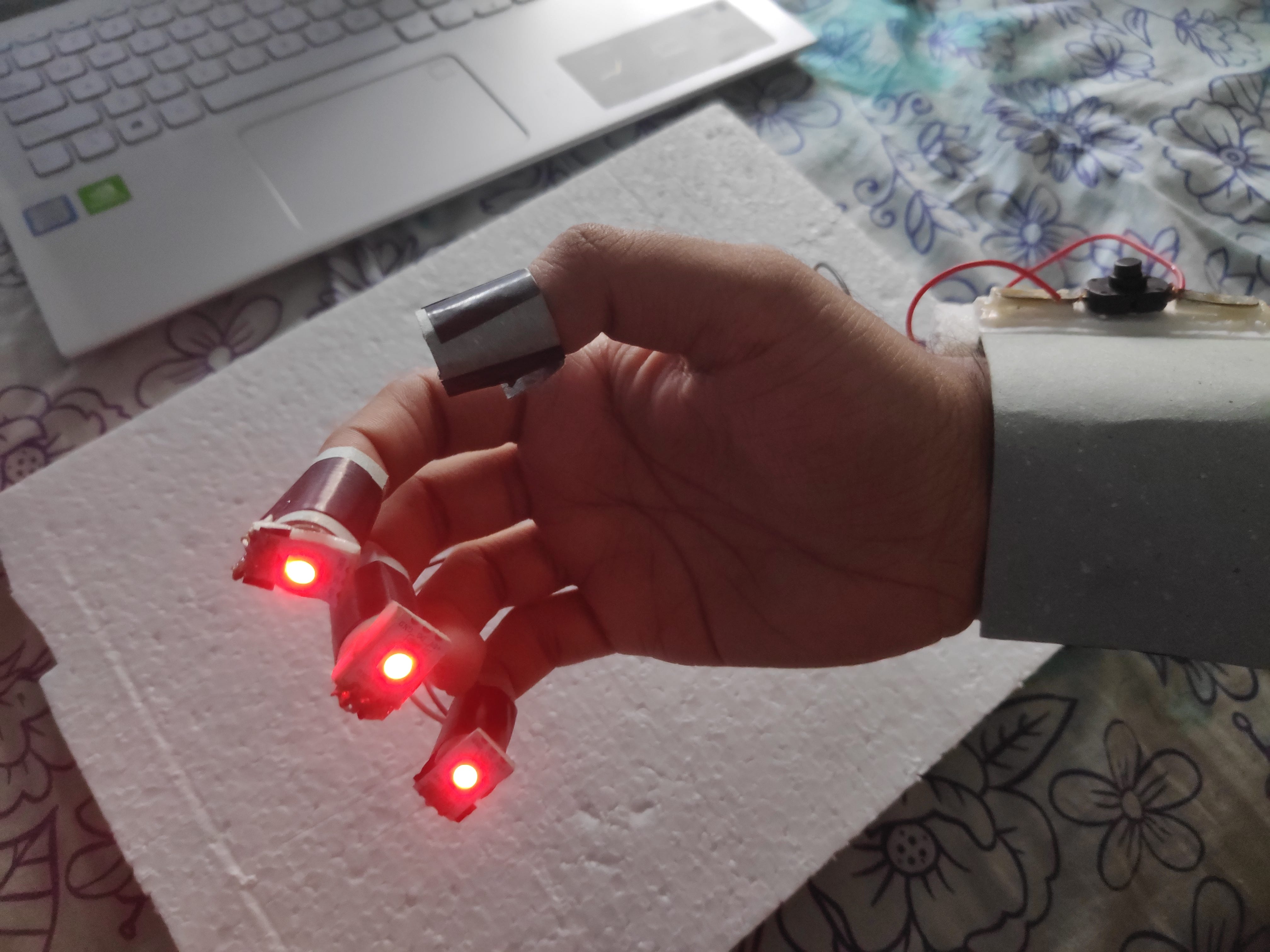
The first thing I decided on were the controls. The current mode was chosen based on the number of fingers extended and the status of a push button. The modes and their respective controls are as follows:
- Normal mouse movement: 1 finger; Move hand to move mouse
- Left mouse press: 1 finger + button; Usable like normal left mouse button
- Zoom in, zoom out: 2 fingers; Move hand up and down to zoom in or out
- Pan: 4 fingers; Move in any direction to pan in that direction
- Rotate: 4 fingers + button; Move hand in direction you want to rotate.
I avoided controls that require the user to raise exactly 3 fingers as it is difficult to move the ring finger completely independently of the little finger.
Communicating with the laptop
The next thing I thought about was how the device was going to interact with the computer. Here are the options I thought about. If there are other possible solutions which I missed (highly likely) please do let me know:
- My previous experience taught me that serial communications between an Arduino and a laptop aren’t always responsive. Small delays may occur. It might have worked fine for this case if I attempted it but I also disliked the idea of the hand being wired to the laptop during operation.
- I probably could have used Bluetooth / transmitter-receiver modules with the Arduino but it’s pretty hard to find any such components these days. Also I didn’t want to make the physical device any bigger than it already is. So that was out of the table.
- Finally, I decided to go with an object detection model that detects LEDs that I’d be fixing on the tips of my fingers. When the button is pressed, the color of the LED changes and the model detects this as a separate object.
The LEDs
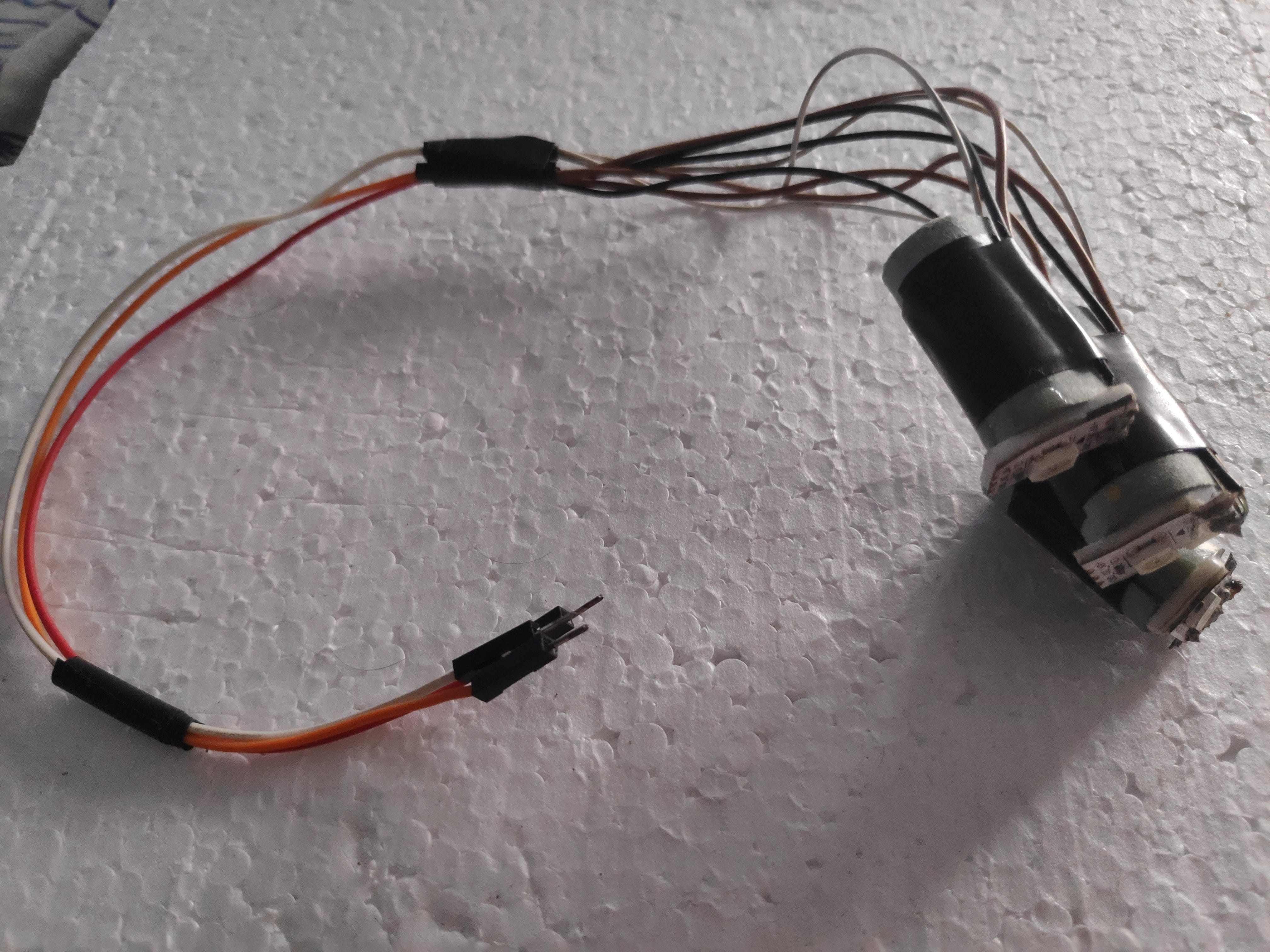
The LEDs I used were from a WS2812B LED strip. These can switch to pretty much any color but I’d be using just blue and red for this project. The good thing about this is that I was able to add more functionality than what I saw in the SpaceX video and I can easily add even more functionality to the device by adding another color and training the model to detect it. I attached these LEDs to pieces of rolled up cardboard so that they can be put on the fingers.
The Microcontroller
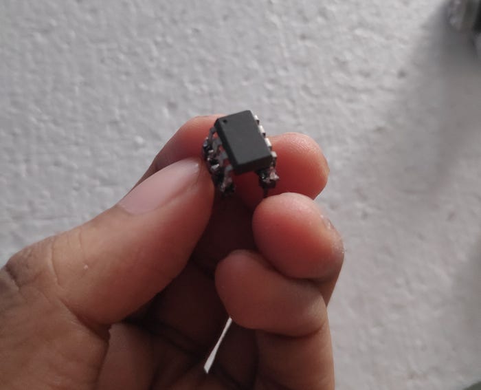
I first decided to use an Arduino to change the color when the button is pressed. This may sound like overkill and in fact, it is. Turns out that a tiny microcontroller that can fit in a fingernail, known as ATtiny85, can replicate the working of an Arduino with only a few drawbacks such as fewer I/O pins. Fortunately, all I needed for this project was a single digital input pin (for the button) and a single digital output pin (for the LEDs). An added advantage is that it can operate with voltages as low as 3V which means you can even power it using an appropriate button cell. In case you want to try something like this, here’s the tutorial I followed to program the ATtiny85. Do let me know in the comments if you face any issues. Also, here’s the code I used with the ATtiny85.
The Button
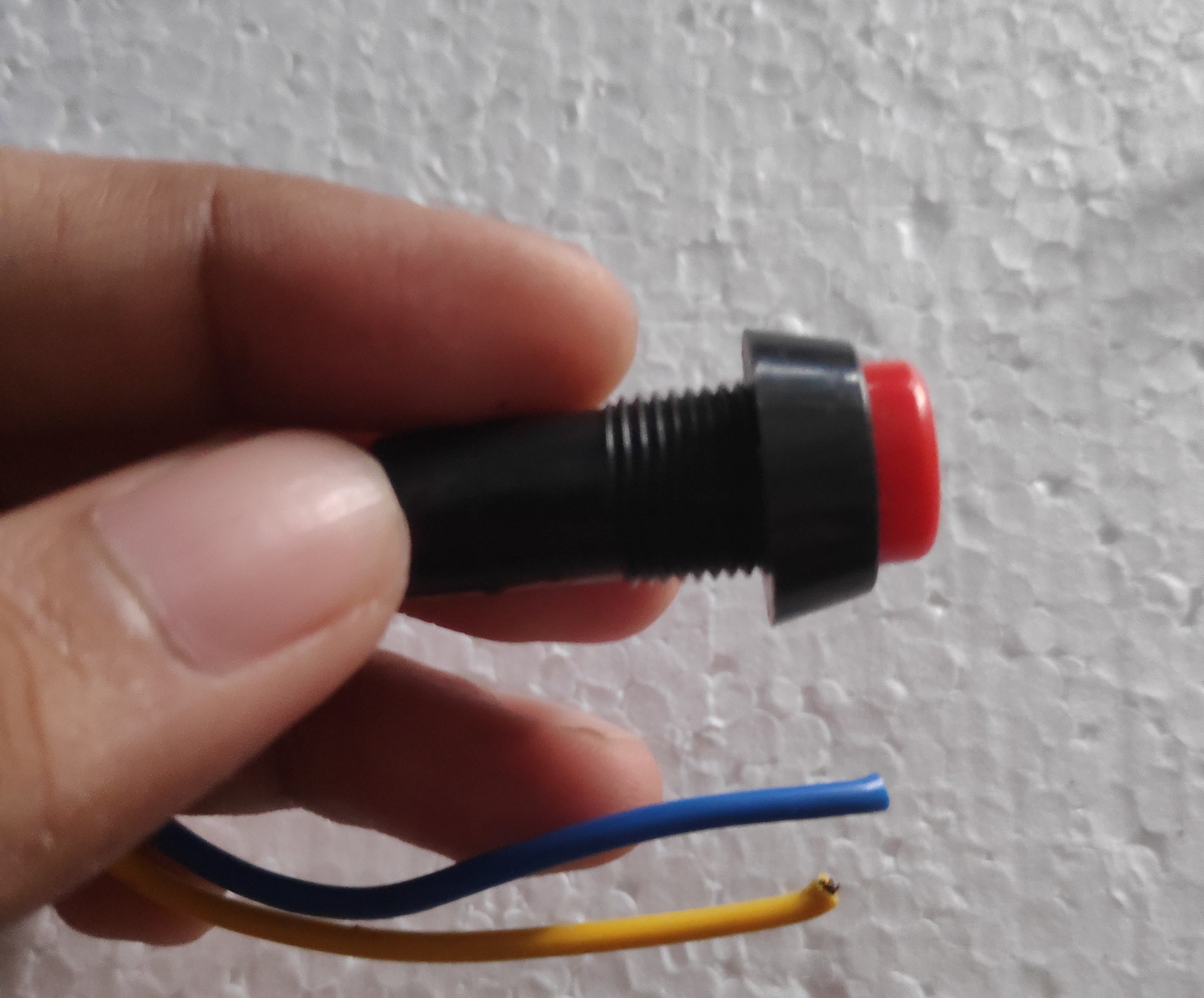
Next, I looked into how I was going to implement the button. I wanted it to be a push button instead of a toggle switch. I actually spent way more time than I should have on this. The problem was that I simply couldn’t find a small enough push button. The only push buttons I found were as wide as a finger.
First I tried making a touch sensor using a transistor. This had 3 problems:
- The voltage change was very small when touched.
- The voltage change varied according to the load. Thus difficult to test.
- The user had to be grounded for it to work.
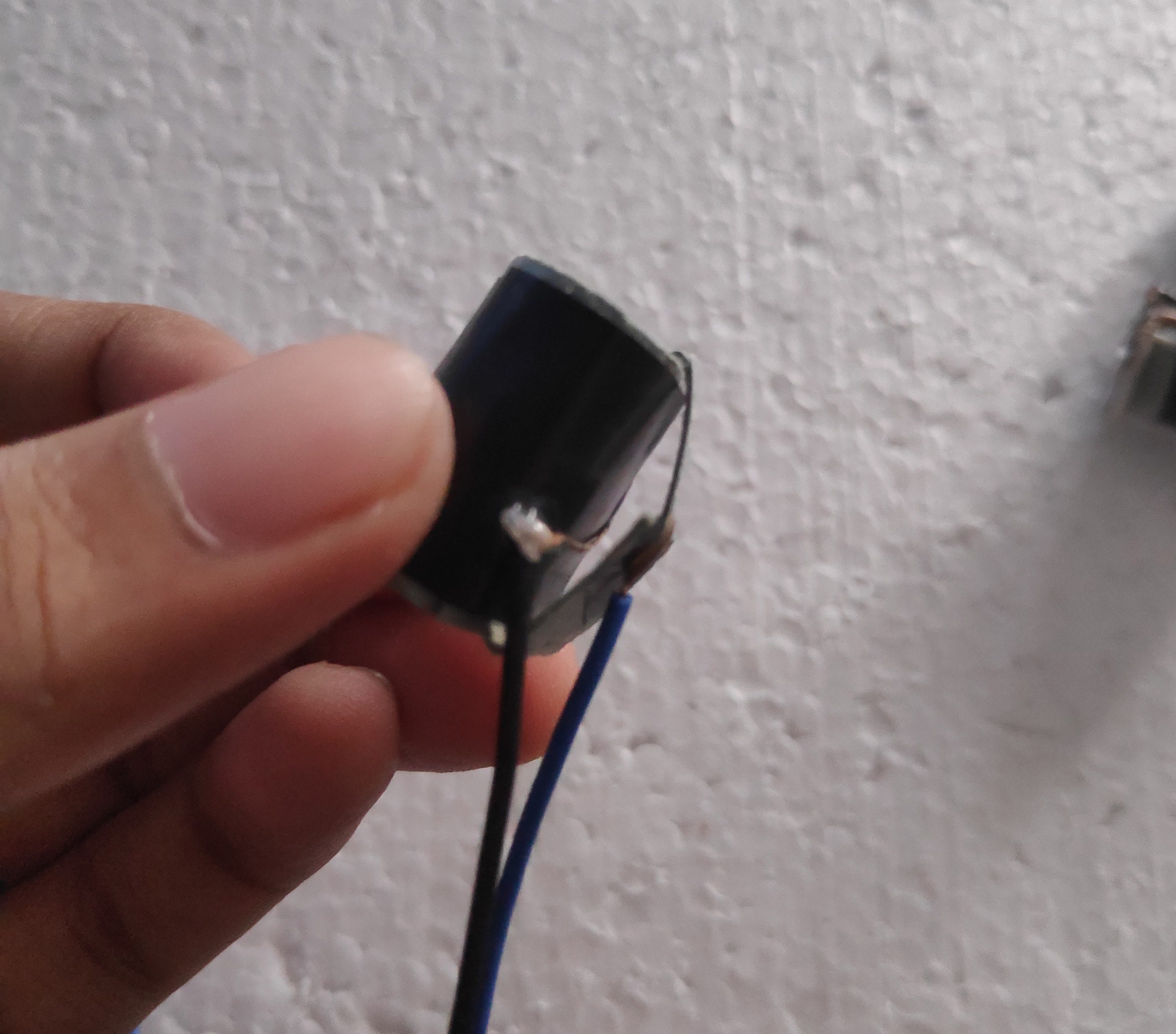
After trying with various resistance values and different Arduino codes, I decided that the simpler option might be the better option. I made a simple touch sensor using cardboard. The thing I have noticed with cardboard is that no matter how hard you press it, or how many times you press it, it’ll never completely fold onto itself. This worked great as a push button.
The Circuit
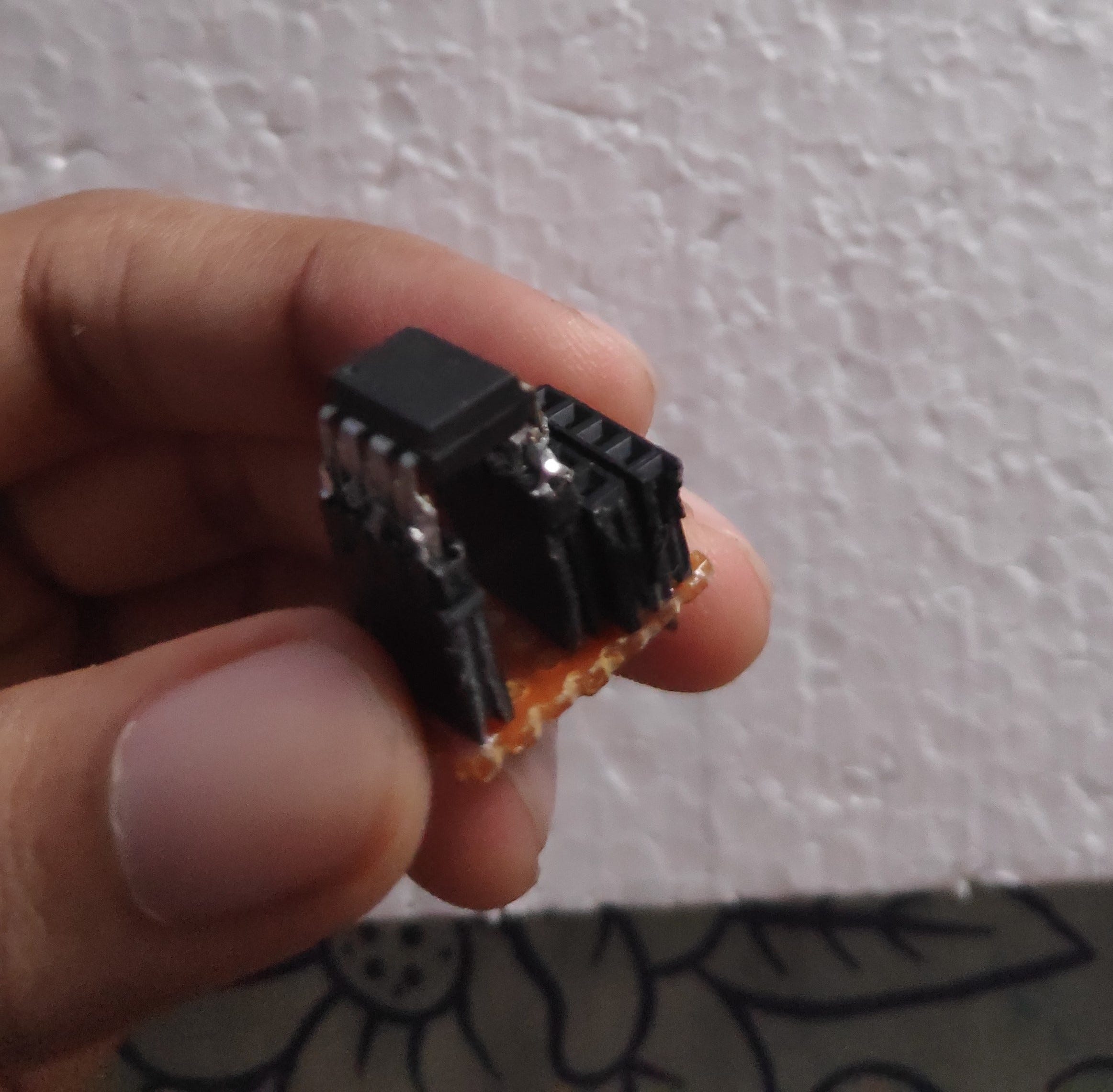
I’m not going to go into too much detail about the circuit diagram. I built it on a strip board and used female pin headers to connect everything so that it’s easier to test and I can reuse any of the components if needed (especially the ATtiny85 of which I found just one). The ATtiny85 has pretty short pins, so I had to solder some male pin headers to be able to use it with the headers. I also did a little trick, where I soldered only the female headers that correspond to the pins of the ATtiny85 that I actually require. This way I was able to manage with just 6 rows on the strip board as opposed to maybe 8 or 9 rows.
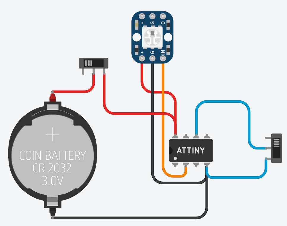
Note: In the circuit diagram above, the slide switch on the right should be a push button. The LED should be a WS2812B LED instead of a NeoPixel and there should be 3 of it. The battery is also different in the actual design. I made the diagram on Tinkercad and these were the only available components that were remotely close to what I required.
The Device
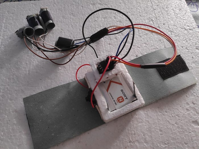
I decided to use a rechargeable battery from an old digital camera because I wanted to be able to test without replacing the battery ever so often. I used foam boards to make a small casing for the battery and the circuit and then I attached it to strip of cardboard to which I also glued two pieces of Velcro to form a wristband. I also attached a toggle switch to the positive voltage wire so that I can power the device on and off when needed.
The Object Detection Model
Now we come in to the software side of things. Like I mentioned before, the object detection model is used to detect the glowing LEDs that are fixed at the tips of the user’s fingers. The model should also be able to differentiate between the two colors (red and blue), as well.
I recorded a video of me moving the device around with both the colors after which I separated the video into frames. Next, I used a software called LabelImg to label all the images in my dataset. This was a pretty tedious task to do, considering I had about 800 images per color. Afterwards, I trained the dataset using the Tensorflow Object Detection API.
Testing the model
The first time I tested the model, the accuracy seemed pretty good. It was only then that I noticed that it’s resolution and the captured camera view were too small. There were also other problems like too many false positives and weakness in detecting the blue LED. I had to test on a larger resolution because that helps support a larger range of hand motion. Unfortunately, the results on the larger model were highly inconsistent with too many false positives and low accuracies.
Next, I tried dividing a high resolution image into 4 smaller images, running object detection on each image individually and then combining them all into one high resolution image. This had a good accuracy as expected. However, the false positives issue was still present. There were also other issues such as:
- Lower framerate
- Inconsistent detections at the margins of the smaller images
Although as a whole this was better than the previous attempts, it was far from ideal.
Next, I went a step back and I decided to retrain the model, now with a lot of data augmentation (changing the images to add different images to the dataset). I let this run overnight and tested the model the next day. What I noticed was that the detection accuracies were extremely low (20–30%) but it was way more consistent (with both colored detections) than the previous model with very few false positives. I didn’t want to train it for longer because I felt that it was too much for my laptop to handle. So I decided to use the same model with a very low detection threshold. I was quite satisfied with the results.
The Code
Once again, I won’t be going too deep into the details of the code. You can take a look at it here. To summarize, these are the steps that are being done by the code.
- Read the image from the camera
- Count the number of detections with accuracy above the threshold and their respective colors. Also eliminate any overlapping detection boxes (This was done by measuring the distance from the center of each box to the center of previously detected boxes and removing if it was greater than a certain threshold).
- The default active color is considered to be red. If a color is seen in 4 subsequent frames, then it is considered to be the current active color.
- Use the library, pyautogui to automate the mouse movements and key presses according to the previously identified active color and detections.
For some reason the “shift” key press of pyautogui didn’t work as expected. This was required for the Pan feature by default. Therefore, I ended up using the “Ctrl” key and then altering the key preferences within blender, instead.
The Results
Here’s a small demonstration of the device.
All in all, I’m quite satisfied with the results. It’s still far from perfect. Current problems of the system and possible solutions are as follows:
- The way I see it, the biggest problem so far is the frame rate. The system runs at about 5–6 fps. This is insufficient for a smooth workflow. However, I believe that this can be resolved by getting the object detection model to run on the cloud. From a previous project that I worked on, I was able to obtain a speedup of approximately 10x by running the object detection on a Kubernetes Cluster on Google Cloud. Take a look at this tutorial if you want to learn more on how this was done.
- A slightly less critical, but nevertheless important problem is the comfortability of the device. The wristband and the finger loops should be made with a more comfortable material than cardboard. The circuit itself is small enough to fit on a finger. If paired with a cell battery, it could be attached to a fourth finger loop which would give a compact device.
- The sensitivities for the controls need a lot of fine tuning. As seen from the above video, the zoom feature is a bit too sensitive to motion. This can be resolved fairly easily by a bit of testing
As seen above, there’s a lot of work that needs to be done if it’s to become a useful product. But I hope that the problems I faced and/or techniques that I used would help someone else when they are working on their own project. Thank you for reading!

